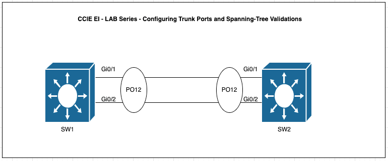
For this post, I will be running lab to configure trunking protocols and validate the spanning-tree.
The task for this lab are the followiing:
- Understand why trunking is required between switches.
- Configure the links between SW1 and SW2 as trunk
- Use dot1q as the encapsulation protocol
- Verify the spanning-tree status of both SW1 and SW2
- Check the status of the ports on both the root-bridge and. non-root bridge.
Access ports can only carry one Data VLAN and one voice VLAN but trunk ports can carry multiple VLANs over ONE physical link.
For example, VLANs 10,20,30 and 40 can be carried on a single physical link through trunking. This can be achieve by configuring the port connected to the other switch using the “switchport mode trunk” command with the industry standard trunking protocol such DOT1Q using the command “switchport mode trunk encapsulation dot1q” under the interface mode.
The question is how does 802.1q tagging works? Essentially when the frame leaves a trunk port(s), the switch will insert a 4 byte header tag into the Ethernet frame.
{Dst MAC} {Src MAC } {802.1Q Tag} {EtherType} {Payload} {FCS}
where the 802.1Q tag has the following fields:
a. TPID ( 16 bit field) that is use to identify the frames as 802.1q taggedb. Priority (Cos) ( 3 bits field) which indicate the 3 bit QoS markingc. DEI or Drop Eligibility Indicator ( 1 bit) which purpose is to check whether a frame can be dropped first during congestion.d. VLAN ID ( 12 bits ) which indicates the VLAN ID
Before configuring the Trunk Ports, let’s validate that SW1 neighbor status with SW2.
SW1#show cdp neighbors
Capability Codes: R – Router, T – Trans Bridge, B – Source Route Bridge
S – Switch, H – Host, I – IGMP, r – Repeater, P – Phone,
D – Remote, C – CVTA, M – Two-port Mac Relay
Device ID Local Intrfce Holdtme Capability Platform Port ID
SW2 Gig 0/1 168 R S I Gig 0/1
SW2 Gig 0/0 136 R S I Gig 0/0
Total cdp entries displayed : 2
From the CDP output, SW1 is connected to SW2 via Gi0/1 and Gi0/2. Now, Let’s check the configuration of the ports on SW1.
SW1#show ru int gi0/1
Building configuration…
Current configuration : 54 bytes
!
interface GigabitEthernet0/1
negotiation auto
end
SW1#show ru int gi0/2
Building configuration…
Current configuration : 54 bytes
!
interface GigabitEthernet0/2
negotiation auto
end
This suggest that SW1 port configs is neither access or trunk ports. But let’s validate the STP status using “show spanning-tree“. The output below suggest that the ports Gi0/1 and Gi0/2 are all in Forwarding state with DESG port role even with a default interface cofigs.
SW1>show spanning-tree
VLAN0001
Spanning tree enabled protocol ieee
Root ID Priority 32769
Address 5000.0001.0000
This bridge is the root
Hello Time 2 sec Max Age 20 sec Forward Delay 15 sec
Bridge ID Priority 32769 (priority 32768 sys-id-ext 1)
Address 5000.0001.0000
Hello Time 2 sec Max Age 20 sec Forward Delay 15 sec
Aging Time 300 sec
Interface Role Sts Cost Prio.Nbr Type
Gi0/0 Desg FWD 4 128.1 P2p
Gi0/1 Desg FWD 4 128.2 P2p
Gi0/2 Desg FWD 4 128.3 P2p
Gi0/3 Desg FWD 4 128.4 P2p
Gi1/0 Desg FWD 4 128.5 P2p
Gi1/1 Desg FWD 4 128.6 P2p
Gi1/2 Desg FWD 4 128.7 P2p
Gi1/3 Desg FWD 4 128.8 P2p
Similarly, let’s check SW2. As shown below, Gi0/0 is showing as the Root Port and is in Forwarding State and Gi0/1 is in Blocking State. From SW2 perspective, SW1 is the Root Switch.
SW2#show spanning-tree
VLAN0001
Spanning tree enabled protocol ieee
Root ID Priority 32769
Address 5000.0001.0000
Cost 4
Port 1 (GigabitEthernet0/0)
Hello Time 2 sec Max Age 20 sec Forward Delay 15 sec
Bridge ID Priority 32769 (priority 32768 sys-id-ext 1)
Address 5000.0002.0000
Hello Time 2 sec Max Age 20 sec Forward Delay 15 sec
Aging Time 300 sec
Interface Role Sts Cost Prio.Nbr Type
Gi0/0 Root FWD 4 128.1 P2p
Gi0/1 Altn BLK 4 128.2 P2p
Gi0/2 Desg FWD 4 128.3 P2p
Gi0/3 Desg FWD 4 128.4 P2p
Gi1/0 Desg FWD 4 128.5 P2p
Gi1/1 Desg FWD 4 128.6 P2p
Gi1/2 Desg FWD 4 128.7 P2p
Interface Role Sts Cost Prio.Nbr Type
Gi1/3 Desg FWD 4 128.8 P2p
SW2#
Main focus why I show this output is to highlight that STP works even if port is not a access port or trunk port but the moment the switch were connected STP kicks in. There will be a separate topic which I will share about STP in details.
Now the main task is to configure Trunking and using DOT1Q protocol.
SW1#config t
SW1(config)#int gi0/1
SW1(config-if)#switchport trunk encapsulation dot1q
SW1(config-if)#switchport mode trunk
SW1(config-if)#int gi0/2
SW1(config-if)#switchport trunk encapsulation dot1q
SW1(config-if)#switchport mode trunk
SW1(config-if)#
SW2(config)#int gi0/1
SW2(config-if)#switchport trunk encapsulation dot1
SW2(config-if)#switchport mode trunk
SW2(config-if)#int gi0/
SW2(config-if)#switchport trunk encapsulation dot1q
SW2(config-if)#switchport mode trunk
Let’s verify the Trunk port status
SW1#sho int trunk
Port Mode Encapsulation Status Native vlan
Gi0/1 on 802.1q trunking 1
Gi0/2 on 802.1q trunking 1
Port Vlans allowed on trunk
Gi0/1 1-4094
Gi0/2 1-4094
Port Vlans allowed and active in management domain
Gi0/1 1
Gi0/2 1
Port Vlans in spanning tree forwarding state and not pruned
Gi0/1 1
Gi0/2 1
SW1#
SW2#show int trunk
Port Mode Encapsulation Status Native vlan
Gi0/1 on 802.1q trunking 1
Gi0/2 on 802.1q trunking 1
Port Vlans allowed on trunk
Gi0/1 1-4094
Gi0/2 1-4094
Port Vlans allowed and active in management domain
Gi0/1 1
Gi0/2 1
Port Vlans in spanning tree forwarding state and not pruned
Gi0/1 none
Gi0/2 1
SW2#
Summary of Configuration Command and Troubleshooting Commands:
Configuration Command:
switchport trunk encapsulation dot1q
switchport mode trunk
Troubleshooting Command:
show interface trunk

Leave a comment