On this post, I wlll be exploring concepts of OSPF network Types and look into some details of some attributes required to established OSPF neighbors.
Key Task:
I will be using the below topology to explore on this lab but for this particular concepts, I will just be using R3, R5 and R6 for this lab both on OSPF process 1. R3 and R5 will be in OSPF area 35 while R5 and R6 will be in OSPF area 56. To explore the ways to enable OSPF, both R3 and R5 will be using the network statement to enable OSPF while for R5 and R6, OSPF will be enabled under interface mode. ALl the loopbacks needs to be advertise on both R3 and R6.
Topology:

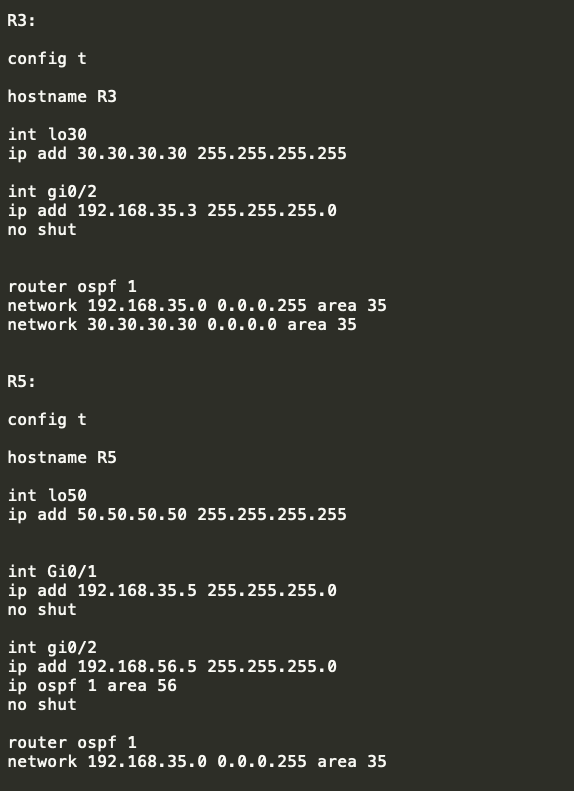
Configurations:

Verifications:
- Verify that the interfaces are assigned on correct ospf areas as per the requirements using “show ip ospf interface brief”


As observed above, the coorect areas were assigned , example for R5 which is the middle router has both areas facing R3 as area 35 and facing R6 as area 56…
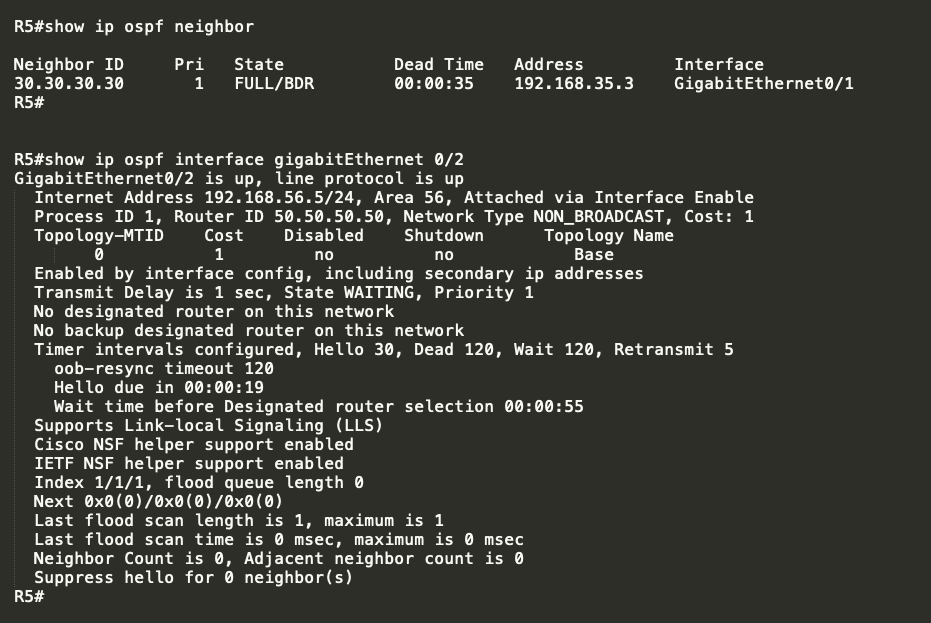
2. Check that the OSPF neighbors were formed:

as observed, OSPF neighbors were formed and R5 is showinga s the DR or designated router..
With the DR/BDR showing on the State, this simply suggest that the OSPF network types were a BROADCAST..
3. To verify the OSPF network type, the command “show ip ospf interface ” can be use.

From the above results, there are several informations provided on the output such as the following:
** The AREA is 56
** Attached via Interface Enable –> this means that the OSPF is enabled under the interface mode using the command “ip ospf 1 area 56”
** The Network Type is BROADCAST
** The OSPF cost is 1
** The Designated Router ID is 50.50.50.50 which is R5.
** The backup designated router is 60.60.60.60 which is R6
** The hello Interval is 10 sec with 40 as the Dead Interval ( which by default will automatically set as 4 times the Hello interval)
4. Lets check the topology table….

>> The Router LSA on area 35 shows two details which is the loopback of R3 and R5 ( this is the router ID of both routers)
>> The Network Link LSA under area 35 also shows the IP address of the R5 which is used to formed the OSPF neighbor. This is local on R5.
>> Similarly, Router LSA on area 56 shows the router ID of R5 and R6
>> The Network Link LSA also shows the IP address of the link on R5 that is used to formed the OSPF neighbors. This is local on R5.
5. Lets check thew routing table by this time…


>> as expected R5 wil learned about R3 and R6 loopbacks as this was advertise from both routers…
>> But R3 and R6 will not learned each other’s loopback as there was no backbone area that was set up..
>> NOTE: OSPF MUST NEED a backbone area in order to provide communications between two different areas.
Let me just advertise R5 loopback on area 35 to elaborate what I mean here…

- Let me explore on checking the two attributes which is required to match (supported) in order to established OSPF neighbors:
*** Network Types
*** Hello Interval
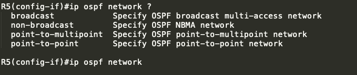
By default, OSPF interface are using BROADCAST….
Let me try changing this to non-broadcast…

As observed the OSPF neighbor towards R6 went …
Lets try to change the network type to point-to-multipoint:
Revert first to Broadcast:

and change to point-to-multipoint

again OSPF does not like it..
Finally, lets try to used “POINT-TO-POINT”

It shows on R5 that a potential network type mistmatch but still it formed the OSPF neighbors…


Leave a comment