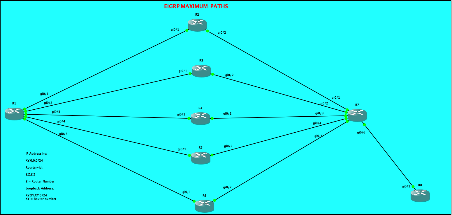
By default, EIGRP have a maximum of four equal cost path for load-balancing traffic. But what if we have more than 4 paths available? EIGRP have this features called “maximum-paths”under EIGRP process which can increased the paths up to 32 equal cost path links.
I’m going to explore this behaviour with 5 equal cost path. For this lab, my task are as follows:
Configure EIGRP on all routers. Conditions as follows:
a. Used network statement “0.0.0.0”on all routers
b. Disable auto-summary
c. Disable all other EIGRP metrics except for delay
Scenario # 1:
Allow all 5 paths between R1 and R7 for load-balancing
Scenario # 2:
Used Paths R1<–> R3<–>R7 and R1<—>R5<—> R7 to become Feasible Successor.
Scenario # 3:
Update the delays so that the feasible successor will do unequal-load balancing with traffic ratio of 5:1 (Successor:Feasible Successor)
| CONFIGURATIONS R1: R1#show ip int brief Interface IP-Address OK? Method Status Protocol GigabitEthernet0/0 10.255.0.233 YES NVRAM administratively down down GigabitEthernet0/1 12.0.0.1 YES NVRAM up up GigabitEthernet0/2 13.0.0.1 YES NVRAM up up GigabitEthernet0/3 14.0.0.1 YES NVRAM up up GigabitEthernet0/4 15.0.0.1 YES NVRAM up up GigabitEthernet0/5 16.0.0.1 YES NVRAM up up Loopback0 1.1.1.1 YES NVRAM up up R1#show run | sec eigrp router eigrp 100 metric weights 0 0 0 1 0 0 network 0.0.0.0 eigrp router-id 1.1.1.1 |
| R2: R2#show ip int brief Interface IP-Address OK? Method Status Protocol GigabitEthernet0/0 10.255.0.234 YES NVRAM administratively down down GigabitEthernet0/1 12.0.0.2 YES NVRAM up up GigabitEthernet0/2 27.0.0.2 YES NVRAM up up R2#show run | sec eigrp router eigrp 100 metric weights 0 0 0 1 0 0 network 0.0.0.0 eigrp router-id 2.2.2.2 |
| R3: R3#show ip int brief Interface IP-Address OK? Method Status Protocol GigabitEthernet0/0 10.255.0.235 YES NVRAM administratively down down GigabitEthernet0/1 13.0.0.3 YES NVRAM up up GigabitEthernet0/2 37.0.0.3 YES NVRAM up up R3#show run | sec eig router eigrp 100 metric weights 0 0 0 1 0 0 network 0.0.0.0 eigrp router-id 3.3.3.3 |
| R4: R4#show ip int brief Interface IP-Address OK? Method Status Protocol GigabitEthernet0/0 10.255.0.236 YES NVRAM administratively down down GigabitEthernet0/1 14.0.0.4 YES NVRAM up up GigabitEthernet0/2 47.0.0.4 YES NVRAM up up R4#sho run | sec eigrp router eigrp 100 metric weights 0 0 0 1 0 0 network 0.0.0.0 eigrp router-id 4.4.4.4 |
| R5: R5#show ip int brief Interface IP-Address OK? Method Status Protocol GigabitEthernet0/0 10.255.0.237 YES NVRAM administratively down down GigabitEthernet0/1 15.0.0.5 YES NVRAM up up GigabitEthernet0/2 57.0.0.5 YES NVRAM up up R5#show run | sec eigrp router eigrp 100 metric weights 0 0 0 1 0 0 network 0.0.0.0 eigrp router-id 5.5.5.5 |
| R6: R6#show ip int brief Interface IP-Address OK? Method Status Protocol GigabitEthernet0/0 10.255.0.238 YES NVRAM administratively down down GigabitEthernet0/1 16.0.0.6 YES NVRAM up up GigabitEthernet0/2 67.0.0.6 YES NVRAM up up R6#show run | sec eigrp router eigrp 100 metric weights 0 0 0 1 0 0 network 0.0.0.0 eigrp router-id 6.6.6.6 |
| R7: R7#show ip int brief Interface IP-Address OK? Method Status Protocol GigabitEthernet0/0 10.255.0.239 YES NVRAM administratively down down GigabitEthernet0/1 27.0.0.7 YES NVRAM up up GigabitEthernet0/2 37.0.0.7 YES NVRAM up up GigabitEthernet0/3 47.0.0.7 YES NVRAM up up GigabitEthernet0/4 57.0.0.7 YES NVRAM up up GigabitEthernet0/5 67.0.0.7 YES NVRAM up up GigabitEthernet0/6 68.0.0.7 YES NVRAM up up R7#show run | sec eigrp router eigrp 100 metric weights 0 0 0 1 0 0 network 0.0.0.0 eigrp router-id 7.7.7.7 |
| R8: R8#show ip int brief Interface IP-Address OK? Method Status Protocol GigabitEthernet0/0 10.255.0.240 YES NVRAM administratively down down GigabitEthernet0/1 68.0.0.8 YES NVRAM up up Loopback8 8.8.8.8 YES NVRAM up up R8#show run | sec eigrp router eigrp 100 metric weights 0 0 0 1 0 0 network 0.0.0.0 eigrp router-id 8.8.8.8 R8# |
From R1 EIGRP topology, it shows 4 successors towards the prefix 8.8.8.8/32
| R1#show ip eigrp topology EIGRP-IPv4 Topology Table for AS(100)/ID(1.1.1.1) Codes: P – Passive, A – Active, U – Update, Q – Query, R – Reply, r – reply Status, s – sia Status P 14.0.0.0/24, 1 successors, FD is 256 via Connected, GigabitEthernet0/3 P 57.0.0.0/24, 1 successors, FD is 512 via 15.0.0.5 (512/256), GigabitEthernet0/4 P 13.0.0.0/24, 1 successors, FD is 256 via Connected, GigabitEthernet0/2 P 15.0.0.0/24, 1 successors, FD is 256 via Connected, GigabitEthernet0/4 P 12.0.0.0/24, 1 successors, FD is 256 via Connected, GigabitEthernet0/1 P 8.8.8.8/32, 4 successors, FD is 128768 via 12.0.0.2 (128768/128512), GigabitEthernet0/1 via 13.0.0.3 (128768/128512), GigabitEthernet0/2 via 14.0.0.4 (128768/128512), GigabitEthernet0/3 via 15.0.0.5 (128768/128512), GigabitEthernet0/4 via 16.0.0.6 (128768/128512), GigabitEthernet0/5 |
We can quickly check the routing table of R1:
| R1#show ip route eigrp | sec 8.8.8.8 D 8.8.8.8 [90/128768] via 15.0.0.5, 03:59:07, GigabitEthernet0/4 [90/128768] via 14.0.0.4, 03:59:07, GigabitEthernet0/3 [90/128768] via 13.0.0.3, 03:59:07, GigabitEthernet0/2 [90/128768] via 12.0.0.2, 03:59:07, GigabitEthernet0/1 27.0.0.0/24 is subnetted, 1 subnets So R1 routing table have installed 4 with equal metrics, though, we can see 5 equal cost-path on the topology table. |
Let’s enable maximum-path and set the value to 5.
| R1#show ip eigrp topology | sec 8.8.8.8 P 8.8.8.8/32, 5 successors, FD is 128768 via 12.0.0.2 (128768/128512), GigabitEthernet0/1 via 13.0.0.3 (128768/128512), GigabitEthernet0/2 via 14.0.0.4 (128768/128512), GigabitEthernet0/3 via 15.0.0.5 (128768/128512), GigabitEthernet0/4 via 16.0.0.6 (128768/128512), GigabitEthernet0/5 R1# As observed, the total successors have increased from 4 to 5. |
What about the routing table of R1?
| R1#show ip route eigrp | sec 8.8.8.8 D 8.8.8.8 [90/128768] via 16.0.0.6, 00:01:46, GigabitEthernet0/5 [90/128768] via 15.0.0.5, 00:01:46, GigabitEthernet0/4 [90/128768] via 14.0.0.4, 00:01:46, GigabitEthernet0/3 [90/128768] via 13.0.0.3, 00:01:46, GigabitEthernet0/2 [90/128768] via 12.0.0.2, 00:01:46, GigabitEthernet0/1 27.0.0.0/24 is subnetted, 1 subnets R1# So by this time we could see that there are 5 available paths on R1’s routing table towards 8.8.8.8/32 This completes the objective for Scenario # 1. — COMPLETED |
Let me modify the delay on all the routers and set it into 3000 microseconds and will be tweaking the delay in order to make R3 and R5 as feasible successors.
| Command: config t int gi0/X where X refers to all the active interfaces.. delay 300 R1: R1#show interfaces gigabitEthernet 0/1 | inc 3000 MTU 1500 bytes, BW 1000000 Kbit/sec, DLY 3000 usec, R1#show interfaces gigabitEthernet 0/2 | inc 3000 MTU 1500 bytes, BW 1000000 Kbit/sec, DLY 3000 usec, R1#show interfaces gigabitEthernet 0/3 | inc 3000 MTU 1500 bytes, BW 1000000 Kbit/sec, DLY 3000 usec, R1#show interfaces gigabitEthernet 0/4 | inc 3000 MTU 1500 bytes, BW 1000000 Kbit/sec, DLY 3000 usec, R1#show interfaces gigabitEthernet 0/5 | inc 3000 MTU 1500 bytes, BW 1000000 Kbit/sec, DLY 3000 usec, R1# R2: R2#show int gigabitEthernet 0/1 | inc 3000 MTU 1500 bytes, BW 1000000 Kbit/sec, DLY 3000 usec, R2# R2#show int gigabitEthernet 0/2 | inc 3000 MTU 1500 bytes, BW 1000000 Kbit/sec, DLY 3000 usec, R2# R3: R3#show interfaces gigabitEthernet 0/1 | inc 3000 MTU 1500 bytes, BW 1000000 Kbit/sec, DLY 3000 usec, R3#show interfaces gigabitEthernet 0/2 | inc 3000 MTU 1500 bytes, BW 1000000 Kbit/sec, DLY 3000 usec, R3# R4: R4#show interfaces gigabitEthernet 0/1 | inc 3000 MTU 1500 bytes, BW 1000000 Kbit/sec, DLY 3000 usec, R4#show interfaces gigabitEthernet 0/2 | inc 3000 MTU 1500 bytes, BW 1000000 Kbit/sec, DLY 3000 usec, R4# R5: R5#show int gigabitEthernet 0/1 | inc 3000 MTU 1500 bytes, BW 1000000 Kbit/sec, DLY 3000 usec, R5#show int gigabitEthernet 0/2 | inc 3000 MTU 1500 bytes, BW 1000000 Kbit/sec, DLY 3000 usec, R5# R6: R6#show int gigabitEthernet 0/1 | inc 3000 MTU 1500 bytes, BW 1000000 Kbit/sec, DLY 3000 usec, R6#show int gigabitEthernet 0/2 | inc 3000 MTU 1500 bytes, BW 1000000 Kbit/sec, DLY 3000 usec, R6# R7: R7#show int gigabitEthernet 0/1 | inc 3000 MTU 1500 bytes, BW 1000000 Kbit/sec, DLY 3000 usec, R7#show int gigabitEthernet 0/2 | inc 3000 MTU 1500 bytes, BW 1000000 Kbit/sec, DLY 3000 usec, R7#show int gigabitEthernet 0/3 | inc 3000 MTU 1500 bytes, BW 1000000 Kbit/sec, DLY 3000 usec, R7#show int gigabitEthernet 0/4 | inc 3000 MTU 1500 bytes, BW 1000000 Kbit/sec, DLY 3000 usec, R7#show int gigabitEthernet 0/5 | inc 3000 MTU 1500 bytes, BW 1000000 Kbit/sec, DLY 3000 usec, R7# R8: R8#show int gigabitEthernet 0/1 | inc 3000 MTU 1500 bytes, BW 1000000 Kbit/sec, DLY 3000 usec, R8# |
Now me change the Delay on the Links between R1 –> R3 –>R7 and also R1 –> R5 –>R7
| I have changed the Delay to 500 on R1, R3, R5 and R7. R1#show run int gigabitEthernet 0/2 Building configuration… Current configuration : 124 bytes ! interface GigabitEthernet0/2 ip address 13.0.0.1 255.255.255.0 delay 500 duplex auto speed auto media-type rj45 end R1#show run int gigabitEthernet 0/4 Building configuration… Current configuration : 124 bytes ! interface GigabitEthernet0/4 ip address 15.0.0.1 255.255.255.0 delay 500 duplex auto speed auto media-type rj45 end R1# R3#show run int gigabitEthernet 0/1 Building configuration… Current configuration : 124 bytes ! interface GigabitEthernet0/1 ip address 13.0.0.2 255.255.255.0 delay 500 duplex auto speed auto media-type rj45 end R3#show run int gigabitEthernet 0/2 Building configuration… Current configuration : 124 bytes ! interface GigabitEthernet0/2 ip address 37.0.0.2 255.255.255.0 delay 500 duplex auto speed auto media-type rj45 end R5#show running-config int gigabitEthernet 0/1 Building configuration… Current configuration : 124 bytes ! interface GigabitEthernet0/1 ip address 15.0.0.2 255.255.255.0 delay 500 duplex auto speed auto media-type rj45 end R5#show running-config int gigabitEthernet 0/2 Building configuration… Current configuration : 124 bytes ! interface GigabitEthernet0/2 ip address 57.0.0.2 255.255.255.0 delay 500 duplex auto speed auto media-type rj45 end R5# R7#show run int gigabitEthernet 0/2 Building configuration… Current configuration : 124 bytes ! interface GigabitEthernet0/2 ip address 37.0.0.7 255.255.255.0 delay 500 duplex auto speed auto media-type rj45 end R7#show run int gigabitEthernet 0/4 Building configuration… Current configuration : 124 bytes ! interface GigabitEthernet0/4 ip address 57.0.0.7 255.255.255.0 delay 500 duplex auto speed auto media-type rj45 end |
Now let check the topology table and routing table of R1..
| R1#show ip eigrp topology all-links | sec 8.8.8.8 P 8.8.8.8/32, 5 successors, FD is 307200, serno 153 via 12.0.0.2 (358400/281600), GigabitEthernet0/1 via 14.0.0.2 (358400/281600), GigabitEthernet0/3 via 16.0.0.2 (358400/281600), GigabitEthernet0/5 via 13.0.0.2 (460800/332800), GigabitEthernet0/2 via 15.0.0.2 (460800/332800), GigabitEthernet0/4 R1# So as observed above, there were 3 successors ( via R2, R4, and R6) which have a lower Feasible Distance than R3 and R5 and as part of the objective for Scenario # 2, we wanted R3 and R5 to be a Feasible Successors. NOTE: It is interesting to see that the eigrp topology mentioned 5 successors, though if we look at the Feasible distance via R3 and R5, it’s higher as compared to the feasible distance via R2, R4 and R6. Does R3 and R5 meets the Feasibility Conditions? Remember the Feasibility Conditions? Ït states that in order to become a Feasible Successor, the Advertised Distance of a candidate feasible successor should be less than the Feasible Distance of the Successor. A.D. ( Feasible Successor) < F.D. ( Successor) So both R3 and R5 have the advertise distance of 332800 towards R1. Take note that 332800 was the Feasible Distance of R3 and R5 towards the prefix 8.8.8.8/32 and this is reported or advertised to R1. So R1 have taken this values as Advertise distance on its topology table from both R3 and R5. R3#show ip eigrp topology | sec 8.8.8.8 P 8.8.8.8/32, 1 successors, FD is 230400 via 37.0.0.7 (332800/204800), GigabitEthernet0/2 R3# R5#sho ip eigrp topology | sec 8.8.8.8 P 8.8.8.8/32, 1 successors, FD is 230400 via 57.0.0.7 (332800/204800), GigabitEthernet0/2 R5# R1 Feasible Distance with respect to R3 and R5 is 460800. R1 Feasible Distance with respect to R2, R4 and R6 is 358400. So with this complex EIGRP metrics computations, we already know that R2, R4 and R6 will be the Successors towards 8.8.8.8/32 while R3 and R5 which meets the Feasibility Conditions will become Feasible Successors. So therefore, we would expect R2, R4 and R6 will be installed on R1 routing table as the equal cost paths towards 8.8.8.8/32. R1#show ip route eigrp | sec 8.8.8.8 D 8.8.8.8 [90/358400] via 16.0.0.2, 00:00:04, GigabitEthernet0/5 [90/358400] via 14.0.0.2, 00:00:04, GigabitEthernet0/3 [90/358400] via 12.0.0.2, 00:00:04, GigabitEthernet0/1 27.0.0.0/24 is subnetted, 1 subnets R1# But as we can see from R1’s routing table, the Feasible Successor is not added yet. So this be need to enable Unequal Cost Path Load Balancing so that it will be installed on R1’s routing table. That requirements will be completed on Scenario # 3. This completes the second scenario for this lab. – COMPLETED |
For the third scenario, I will need to update the variance in order to have an unequal cost path load balancing. Meaning, I would expect that R3 and R5 paths will also be installed on R1’s routing table.
| So what is the rule for Unequal Cost Path Load Balancing? “The rule states that the Feasible Distance of Feasible Successor should be less than the Feasible Distance of a Successor times a variance multiplier.” Mathematically, F.D. ( Feasible Successor) < F.D. ( Successor) * Variance So variance is important in order to configure Unequal Cost Path Load Balancing in EIGRP. This can be applied under EIGRP process as shown below, R1(config)#router eigrp 100 R1(config-router)#variance ? <1-128> Metric variance multiplier R1(config-router)#variance So from R1 perspective, the Feasible Distance of the Feasible Successors ( R3 and R5) is 460800 while the Feasible Distance of Successors ( R2, R4 and R6) is 358400. So mathematically, I can set a variance of 2 in order to meet the conditions. 460800 < 358400 * 2 460800 < 716800 So what I did is I have multiplied 358400 * 2 = 716800 R1(config)#router eigrp 100 R1(config-router)#variance 2 Now, from R1 routing table , it already shows 5 paths to reach 8.8.8.8/32. Variance of 2 have allowed this happen though as observed those 5 paths have indicated the feasible distance are not the same. R1#show ip route eigrp | sec 8.8.8.8 D 8.8.8.8 [90/358400] via 16.0.0.2, 00:00:55, GigabitEthernet0/5 [90/460800] via 15.0.0.2, 00:00:55, GigabitEthernet0/4 [90/358400] via 14.0.0.2, 00:00:55, GigabitEthernet0/3 [90/460800] via 13.0.0.2, 00:00:55, GigabitEthernet0/2 [90/358400] via 12.0.0.2, 00:00:55, GigabitEthernet0/1 27.0.0.0/24 is subnetted, 1 subnets R1# So I think we are done on the Non-Equal Cost Path configurations but the Scenario # 3 objective is to have as much as 5 times amount of traffic for R2, R4 and R6 as compared to the amount of traffic carried by R3 and R5. So The next action that we can do is to play with the the variance or with the delay on the interface. So what will gonna happen if I will increased the variance to 25…. R1(config)#router eigrp 100 R1(config-router)#variance 25 R1(config-router)#^Z R1#sh *Jun 1 14:52:33.652: %SYS-5-CONFIG_I: Configured from console by cons R1#show ip eigrp topology | sec 8.8.8.8 P 8.8.8.8/32, 5 successors, FD is 358400 via 12.0.0.2 (358400/281600), GigabitEthernet0/1 via 14.0.0.2 (358400/281600), GigabitEthernet0/3 via 16.0.0.2 (358400/281600), GigabitEthernet0/5 via 13.0.0.2 (460800/332800), GigabitEthernet0/2 via 15.0.0.2 (460800/332800), GigabitEthernet0/4 R1# As observed increasing the variance to 25 does not change the Feasible distance… So that means, I can play around with the delay. So if we look at the Metrics calculations, Delay is propotional to the overall metrics, meaning increasing the delay would mean an increased on the metrics. Now since, I wanted to have an amount of traffic of 5 times as much for R2, R4 and R6, it means that I would need to have a feasible distance for R3 and R5 which is 5 times the current feasible distance of R2, R4, and R6…Does this makes since? Lets check the current traffic share of all the 5 routers from R1’s perspective.. R1#show ip route 8.8.8.8 Routing entry for 8.8.8.8/32 Known via “eigrp 100”, distance 90, metric 358400, type internal Redistributing via eigrp 100 Last update from 14.0.0.2 on GigabitEthernet0/3, 00:06:15 ago Routing Descriptor Blocks: 16.0.0.2, from 16.0.0.2, 00:06:15 ago, via GigabitEthernet0/5 Route metric is 358400, traffic share count is 240 Total delay is 14000 microseconds, minimum bandwidth is 1000000 Kbit Reliability 252/255, minimum MTU 1500 bytes Loading 1/255, Hops 3 15.0.0.2, from 15.0.0.2, 00:06:15 ago, via GigabitEthernet0/4 Route metric is 460800, traffic share count is 187 Total delay is 18000 microseconds, minimum bandwidth is 1000000 Kbit Reliability 253/255, minimum MTU 1500 bytes Loading 1/255, Hops 3 14.0.0.2, from 14.0.0.2, 00:06:15 ago, via GigabitEthernet0/3 Route metric is 358400, traffic share count is 240 Total delay is 14000 microseconds, minimum bandwidth is 1000000 Kbit Reliability 253/255, minimum MTU 1500 bytes Loading 1/255, Hops 3 13.0.0.2, from 13.0.0.2, 00:06:15 ago, via GigabitEthernet0/2 Route metric is 460800, traffic share count is 187 Total delay is 18000 microseconds, minimum bandwidth is 1000000 Kbit Reliability 253/255, minimum MTU 1500 bytes Loading 1/255, Hops 3 12.0.0.2, from 12.0.0.2, 00:06:15 ago, via GigabitEthernet0/1 Route metric is 358400, traffic share count is 240 Total delay is 14000 microseconds, minimum bandwidth is 1000000 Kbit Reliability 251/255, minimum MTU 1500 bytes Loading 1/255, Hops 3 R1# As can be seen above, the traffic shares of R2, R4 and R6 is 240 while R3 and R5 have 187… So let me increased the delay on R1 links towards R3 and R4 so it will less likely preferred and thus increasing the traffic shares on R2, R4 and R6. R1#config t Enter configuration commands, one per line. End with CNTL/Z. R1(config)#int gi0/2 R1(config-if)#delay 6000 R1(config-if)#int gi0/4 R1(config-if)#delay 6000 R1(config-if)#^Z R1# I have played around on the delay value and came up with 6000 which provides a share of closed to 5:1. R1#show ip route 8.8.8.8 Routing entry for 8.8.8.8/32 Known via “eigrp 100”, distance 90, metric 358400, type internal Redistributing via eigrp 100 Last update from 15.0.0.2 on GigabitEthernet0/4, 00:01:57 ago Routing Descriptor Blocks: 16.0.0.2, from 16.0.0.2, 00:01:57 ago, via GigabitEthernet0/5 Route metric is 358400, traffic share count is 120 Total delay is 14000 microseconds, minimum bandwidth is 1000000 Kbit Reliability 252/255, minimum MTU 1500 bytes Loading 1/255, Hops 3 15.0.0.2, from 15.0.0.2, 00:01:57 ago, via GigabitEthernet0/4 Route metric is 1868800, traffic share count is 23 Total delay is 73000 microseconds, minimum bandwidth is 1000000 Kbit Reliability 253/255, minimum MTU 1500 bytes Loading 1/255, Hops 3 14.0.0.2, from 14.0.0.2, 00:01:57 ago, via GigabitEthernet0/3 Route metric is 358400, traffic share count is 120 Total delay is 14000 microseconds, minimum bandwidth is 1000000 Kbit Reliability 253/255, minimum MTU 1500 bytes Loading 1/255, Hops 3 13.0.0.2, from 13.0.0.2, 00:01:57 ago, via GigabitEthernet0/2 Route metric is 1868800, traffic share count is 23 Total delay is 73000 microseconds, minimum bandwidth is 1000000 Kbit Reliability 253/255, minimum MTU 1500 bytes Loading 1/255, Hops 3 12.0.0.2, from 12.0.0.2, 00:01:57 ago, via GigabitEthernet0/1 Route metric is 358400, traffic share count is 120 Total delay is 14000 microseconds, minimum bandwidth is 1000000 Kbit Reliability 251/255, minimum MTU 1500 bytes Loading 1/255, Hops 3 R1# R1#show ip route eigrp | sec 8.8.8.8 D 8.8.8.8 [90/358400] via 16.0.0.2, 00:03:21, GigabitEthernet0/5 [90/1868800] via 15.0.0.2, 00:03:21, GigabitEthernet0/4 [90/358400] via 14.0.0.2, 00:03:21, GigabitEthernet0/3 [90/1868800] via 13.0.0.2, 00:03:21, GigabitEthernet0/2 [90/358400] via 12.0.0.2, 00:03:21, GigabitEthernet0/1 27.0.0.0/24 is subnetted, 1 subnets R1# This completes the third scenario for this lab. – COMPLETED |

Leave a comment