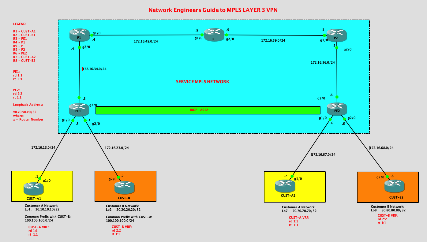
Legend:
R1 – CUST-A1
R2 – CUST-B1
R3 – PE1
R4 – P1
R9 – P
R5 – P2
R6 – PE2
R7 – CUST-A2
R8 – CUST-B2
MPLS – NETWORK
R3 = PE1
|
PE1#show ip int brief
Interface IP-Address OK? Method Status Protocol FastEthernet0/0 unassigned YES unset administratively down down GigabitEthernet1/0 172.16.13.3 YES manual up up GigabitEthernet2/0 172.16.23.3 YES manual up up GigabitEthernet3/0 172.16.34.3 YES manual up up Loopback3 30.30.30.30 YES manual up up router ospf 1 network 30.30.30.30 0.0.0.0
area 0 network 172.16.34.0 0.0.0.255 area 0 interface GigabitEthernet3/0
ip address 172.16.34.3 255.255.255.0 ip ospf priority 0 negotiation auto mpls ip |
R4 = P1
|
P1#show ip int brief
Interface IP-Address OK? Method Status Protocol FastEthernet0/0 unassigned YES unset administratively down down GigabitEthernet1/0 172.16.49.4 YES manual up up GigabitEthernet2/0 172.16.34.4 YES manual up up Loopback4 40.40.40.40 YES manual up up router ospf 1
network 40.40.40.40 0.0.0.0 area 0 network 172.16.34.0 0.0.0.255 area 0 network 172.16.49.0 0.0.0.255 area 0 mpls ldp autoconfig |
R9 = P
|
P#show ip int brief
Interface IP-Address OK? Method Status Protocol FastEthernet0/0 unassigned YES unset administratively down down GigabitEthernet1/0 172.16.49.9 YES manual up up GigabitEthernet2/0 172.16.59.9 YES manual up up Loopback9 90.90.90.90 YES manual up up router ospf 1 network 90.90.90.90 0.0.0.0
area 0 network 172.16.49.0 0.0.0.255 area 0 network 172.16.59.0 0.0.0.255 area 0 mpls ldp autoconfig |
R5 = P2
|
P2#show ip int brief
Interface IP-Address OK? Method Status Protocol FastEthernet0/0 unassigned YES unset administratively down down GigabitEthernet1/0 172.16.59.5 YES manual up up GigabitEthernet2/0 172.16.56.5 YES manual up up Loopback5 50.50.50.50 YES manual up up router ospf 1 network 50.50.50.50 0.0.0.0 area 0
network 172.16.56.0 0.0.0.255 area 0 network 172.16.59.0 0.0.0.255 area 0 mpls ldp autoconfig |
R6 = PE2
|
PE2#show ip int brief
Interface IP-Address OK? Method Status Protocol FastEthernet0/0 unassigned YES unset administratively down down GigabitEthernet1/0 172.16.67.6 YES manual up up GigabitEthernet2/0 172.16.68.6 YES manual up up GigabitEthernet3/0 172.16.56.6 YES manual up up Loopback6 60.60.60.60 YES manual up up interface GigabitEthernet3/0
ip address 172.16.56.6 255.255.255.0 negotiation auto mpls ip router ospf 1 network 60.60.60.60 0.0.0.0 area 0 network 172.16.56.0 0.0.0.255 area 0 |
Customer VRF Configurations:
R3 = PE1
|
ip vrf CUST-A
rd 1:1 route-target export 1:1 route-target import 1:1 ! ip vrf CUST-B rd 2:2 interface GigabitEthernet1/0
ip vrf forwarding CUST-A ip address 172.16.13.3 255.255.255.0 negotiation auto interface GigabitEthernet2/0
ip vrf forwarding CUST-B ip address 172.16.23.3 255.255.255.0 negotiation auto |
R6 = PE2
|
ip vrf CUST-A rd 1:1
route-target export 1:1 route-target import 1:1 ip vrf CUST-B interface GigabitEthernet1/0
ip vrf forwarding CUST-A ip address 172.16.67.6 255.255.255.0 negotiation auto ! interface GigabitEthernet2/0 |
IBGP and MP-BGP Configurations between PE1 and PE2:
R3 = PE1
|
router bgp 12
bgp log-neighbor-changes neighbor 60.60.60.60 remote-as 12 neighbor 60.60.60.60 update-source Loopback3 ! address-family ipv4 no neighbor 60.60.60.60 activate exit-address-family ! address-family vpnv4 neighbor 60.60.60.60 activate neighbor 60.60.60.60 send-community extended exit-address-family ! |
R6 = PE2
|
router bgp 12
bgp log-neighbor-changes neighbor 30.30.30.30 remote-as 12 neighbor 30.30.30.30 update-source Loopback6 ! address-family ipv4 no neighbor 30.30.30.30 activate exit-address-family ! address-family vpnv4 neighbor 30.30.30.30 activate neighbor 30.30.30.30 send-community extended exit-address-family |
EBGP Configurations between PE’s and CE’s:
R1 = CUST-A-HQ
|
router bgp 100
bgp log-neighbor-changes network 10.10.10.10 mask 255.255.255.255 network 100.100.100.0 mask 255.255.255.0 neighbor 172.16.13.3 remote-as 12 |
R7 = CUST-A-BRANCH
|
router bgp 700
bgp log-neighbor-changes network 70.70.70.70 mask 255.255.255.255 neighbor 172.16.67.6 remote-as 12 |
R2 = CUST-B-HQ
|
router bgp 200
bgp log-neighbor-changes network 20.20.20.20 mask 255.255.255.255 network 100.100.100.0 mask 255.255.255.0 neighbor 172.16.23.3 remote-as 12 |
R8 = CUST-B-BRANCH
|
router bgp 800
bgp log-neighbor-changes network 80.80.80.80 mask 255.255.255.255 neighbor 172.16.68.6 remote-as 12 |
Let’s check the eBGP PE router configurations towards the CE’s:
R3 = PE1
|
address-family ipv4 vrf CUST-A
neighbor 172.16.13.1 remote-as 100 neighbor 172.16.13.1 activate exit-address-family ! address-family ipv4 vrf CUST-B neighbor 172.16.23.2 remote-as 200 neighbor 172.16.23.2 activate exit-address-family |
R6 = PE2
|
address-family ipv4 vrf CUST-A
neighbor 172.16.67.7 remote-as 700 neighbor 172.16.67.7 activate exit-address-family ! address-family ipv4 vrf CUST-B neighbor 172.16.68.8 remote-as 800 neighbor 172.16.68.8 activate exit-address-family |
Verification:
Let me check the MPLS CORE routers:
|
OSPF Neighbors
P#show ip ospf neighbor
Neighbor ID Pri State Dead Time Address Interface 50.50.50.50 1 FULL/BDR 00:00:38 172.16.59.5 GigabitEthernet2/0 40.40.40.40 1 FULL/BDR 00:00:37 172.16.49.4 GigabitEthernet1/0 After LDP is enabled:
P#show mpls ldp neighbor
Peer LDP Ident: 40.40.40.40:0; Local LDP Ident 90.90.90.90:0 TCP connection: 40.40.40.40.646 – 90.90.90.90.65164 State: Oper; Msgs sent/rcvd: 309/312; Downstream Up time: 04:20:38 LDP discovery sources: GigabitEthernet1/0, Src IP addr: 172.16.49.4 Addresses bound to peer LDP Ident: 172.16.49.4 172.16.34.4 40.40.40.40 Peer LDP Ident: 50.50.50.50:0; Local LDP Ident 90.90.90.90:0 TCP connection: 50.50.50.50.646 – 90.90.90.90.22167 State: Oper; Msgs sent/rcvd: 310/306; Downstream Up time: 04:19:49 LDP discovery sources: GigabitEthernet2/0, Src IP addr: 172.16.59.5 Addresses bound to peer LDP Ident: 172.16.59.5 172.16.56.5 50.50.50.50 P1#show ip ospf neighbor
Neighbor ID Pri State Dead Time Address Interface P1#show mpls ldp neighbor
Peer LDP Ident: 90.90.90.90:0; Local LDP Ident 40.40.40.40:0 TCP connection: 90.90.90.90.65164 – 40.40.40.40.646 State: Oper; Msgs sent/rcvd: 312/310; Downstream Up time: 04:21:09 LDP discovery sources: GigabitEthernet1/0, Src IP addr: 172.16.49.9 Addresses bound to peer LDP Ident: 172.16.49.9 172.16.59.9 90.90.90.90 Peer LDP Ident: 30.30.30.30:0; Local LDP Ident 40.40.40.40:0 TCP connection: 30.30.30.30.646 – 40.40.40.40.24711 State: Oper; Msgs sent/rcvd: 305/305; Downstream Up time: 04:17:34 LDP discovery sources: GigabitEthernet2/0, Src IP addr: 172.16.34.3 Addresses bound to peer LDP Ident: 172.16.34.3 30.30.30.30 P1# P2#show ip ospf neighbor
Neighbor ID Pri State Dead Time Address Interface P2#show mpls ldp neighbor
Peer LDP Ident: 90.90.90.90:0; Local LDP Ident 50.50.50.50:0 TCP connection: 90.90.90.90.22167 – 50.50.50.50.646 State: Oper; Msgs sent/rcvd: 307/312; Downstream Up time: 04:20:51 LDP discovery sources: GigabitEthernet1/0, Src IP addr: 172.16.59.9 Addresses bound to peer LDP Ident: 172.16.49.9 172.16.59.9 90.90.90.90 Peer LDP Ident: 60.60.60.60:0; Local LDP Ident 50.50.50.50:0 TCP connection: 60.60.60.60.51680 – 50.50.50.50.646 State: Oper; Msgs sent/rcvd: 309/309; Downstream Up time: 04:20:33 LDP discovery sources: GigabitEthernet2/0, Src IP addr: 172.16.56.6 Addresses bound to peer LDP Ident: 172.16.56.6 60.60.60.60 P2# |
|
Note:
|
Now let me verify the iBGP and MP-BGP routes on the PE’s:
|
As observed below, since we enabled MP-BGP for VRF CUST-A, we can see that the the BGP neighbor is established for CE1.
PE1#show bgp vpnv4 unicast vrf CUST-A summary
BGP router identifier 30.30.30.30, local AS number 12 BGP table version is 11, main routing table version 11 3 network entries using 468 bytes of memory 3 path entries using 240 bytes of memory 6/4 BGP path/bestpath attribute entries using 864 bytes of memory 4 BGP AS-PATH entries using 96 bytes of memory 2 BGP extended community entries using 48 bytes of memory 0 BGP route-map cache entries using 0 bytes of memory 0 BGP filter-list cache entries using 0 bytes of memory BGP using 1716 total bytes of memory BGP activity 7/1 prefixes, 7/1 paths, scan interval 60 secs Neighbor V AS MsgRcvd MsgSent TblVer InQ OutQ Up/Down State/PfxRcd 172.16.13.1 4 100 424 422 11 0 0 06:19:54 2 PE1# PE1#show bgp vpnv4 unicast vrf CUST-B summary BGP router identifier 30.30.30.30, local AS number 12 BGP table version is 11, main routing table version 11 3 network entries using 468 bytes of memory 3 path entries using 240 bytes of memory 6/4 BGP path/bestpath attribute entries using 864 bytes of memory 4 BGP AS-PATH entries using 96 bytes of memory 2 BGP extended community entries using 48 bytes of memory 0 BGP route-map cache entries using 0 bytes of memory 0 BGP filter-list cache entries using 0 bytes of memory BGP using 1716 total bytes of memory BGP activity 7/1 prefixes, 7/1 paths, scan interval 60 secs Neighbor V AS MsgRcvd MsgSent TblVer InQ OutQ Up/Down State/PfxRcd 172.16.23.2 4 200 389 390 11 0 0 05:48:43 2 Checking the prefixes advertised on each customer VRF’s:
PE1#show bgp vpnv4 unicast all
BGP table version is 11, local router ID is 30.30.30.30 Status codes: s suppressed, d damped, h history, * valid, > best, i – internal, r RIB-failure, S Stale, m multipath, b backup-path, f RT-Filter, x best-external, a additional-path, c RIB-compressed, Origin codes: i – IGP, e – EGP, ? – incomplete RPKI validation codes: V valid, I invalid, N Not found Network Next Hop Metric LocPrf Weight Path Route Distinguisher: 1:1 (default for vrf CUST-A) *> 10.10.10.10/32 172.16.13.1 0 0 100 i *>i 70.70.70.70/32 60.60.60.60 0 100 0 700 i *> 100.100.100.0/24 172.16.13.1 0 0 100 i Route Distinguisher: 2:2 (default for vrf CUST-B) *> 20.20.20.20/32 172.16.23.2 0 0 200 i *>i 80.80.80.80/32 60.60.60.60 0 100 0 800 i *> 100.100.100.0/24 172.16.23.2 0 0 200 i PE1# Checking on PE2,
PE2#show bgp vpnv4 unicast vrf CUST-A summary
BGP router identifier 60.60.60.60, local AS number 12 BGP table version is 14, main routing table version 14 3 network entries using 468 bytes of memory 3 path entries using 240 bytes of memory 6/4 BGP path/bestpath attribute entries using 864 bytes of memory 4 BGP AS-PATH entries using 96 bytes of memory 2 BGP extended community entries using 48 bytes of memory 0 BGP route-map cache entries using 0 bytes of memory 0 BGP filter-list cache entries using 0 bytes of memory BGP using 1716 total bytes of memory BGP activity 7/1 prefixes, 7/1 paths, scan interval 60 secs Neighbor V AS MsgRcvd MsgSent TblVer InQ OutQ Up/Down State/PfxRcd 172.16.67.7 4 700 371 373 14 0 0 05:33:41 1 PE2#show bgp vpnv4 unicast vrf CUST-B summary BGP router identifier 60.60.60.60, local AS number 12 BGP table version is 14, main routing table version 14 3 network entries using 468 bytes of memory 3 path entries using 240 bytes of memory 6/4 BGP path/bestpath attribute entries using 864 bytes of memory 4 BGP AS-PATH entries using 96 bytes of memory 2 BGP extended community entries using 48 bytes of memory 0 BGP route-map cache entries using 0 bytes of memory 0 BGP filter-list cache entries using 0 bytes of memory BGP using 1716 total bytes of memory BGP activity 7/1 prefixes, 7/1 paths, scan interval 60 secs Neighbor V AS MsgRcvd MsgSent TblVer InQ OutQ Up/Down State/PfxRcd 172.16.68.8 4 800 389 393 14 0 0 05:50:50 1 PE2# PE2#show bgp vpnv4 unicast all BGP table version is 14, local router ID is 60.60.60.60 Status codes: s suppressed, d damped, h history, * valid, > best, i – internal, r RIB-failure, S Stale, m multipath, b backup-path, f RT-Filter, x best-external, a additional-path, c RIB-compressed, Origin codes: i – IGP, e – EGP, ? – incomplete RPKI validation codes: V valid, I invalid, N Not found Network Next Hop Metric LocPrf Weight Path Route Distinguisher: 1:1 (default for vrf CUST-A) *>i 10.10.10.10/32 30.30.30.30 0 100 0 100 i *> 70.70.70.70/32 172.16.67.7 0 0 700 i *>i 100.100.100.0/24 30.30.30.30 0 100 0 100 i Route Distinguisher: 2:2 (default for vrf CUST-B) *>i 20.20.20.20/32 30.30.30.30 0 100 0 200 i *> 80.80.80.80/32 172.16.68.8 0 0 800 i *>i 100.100.100.0/24 30.30.30.30 0 100 0 200 i PE2# As we can see above, all the Prefixes that were advertised by the CE’s are all on the PE’s routing table.
Now let’s check the CE routing table. I would expect on CE1 ( CUST-A1) to have the 70.70.70.70/32 network as that is being advertised by CUST-A2.
CUST-A1#show ip route bgp
Codes: L – local, C – connected, S – static, R – RIP, M – mobile, B – BGP D – EIGRP, EX – EIGRP external, O – OSPF, IA – OSPF inter area N1 – OSPF NSSA external type 1, N2 – OSPF NSSA external type 2 E1 – OSPF external type 1, E2 – OSPF external type 2 i – IS-IS, su – IS-IS summary, L1 – IS-IS level-1, L2 – IS-IS level-2 ia – IS-IS inter area, * – candidate default, U – per-user static route o – ODR, P – periodic downloaded static route, H – NHRP, l – LISP + – replicated route, % – next hop override Gateway of last resort is not set 70.0.0.0/32 is subnetted, 1 subnets B 70.70.70.70 [20/0] via 172.16.13.3, 05:34:39 CUST-A1# Similarly, CUST-A2 is also receiving the prefix advertised by CUST-A1.
CUST-A2#show ip route bgp
Codes: L – local, C – connected, S – static, R – RIP, M – mobile, B – BGP D – EIGRP, EX – EIGRP external, O – OSPF, IA – OSPF inter area N1 – OSPF NSSA external type 1, N2 – OSPF NSSA external type 2 E1 – OSPF external type 1, E2 – OSPF external type 2 i – IS-IS, su – IS-IS summary, L1 – IS-IS level-1, L2 – IS-IS level-2 ia – IS-IS inter area, * – candidate default, U – per-user static route o – ODR, P – periodic downloaded static route, H – NHRP, l – LISP + – replicated route, % – next hop override Gateway of last resort is not set 10.0.0.0/32 is subnetted, 1 subnets B 10.10.10.10 [20/0] via 172.16.67.6, 05:35:00 100.0.0.0/24 is subnetted, 1 subnets B 100.100.100.0 [20/0] via 172.16.67.6, 05:32:57 CUST-A2# This should be the same prefix that is being advertised by PE2:
PE2#show bgp vpnv4 unicast vrf CUST-A neighbors 172.16.67.7 advertised-routes
BGP table version is 14, local router ID is 60.60.60.60 Status codes: s suppressed, d damped, h history, * valid, > best, i – internal, r RIB-failure, S Stale, m multipath, b backup-path, f RT-Filter, x best-external, a additional-path, c RIB-compressed, Origin codes: i – IGP, e – EGP, ? – incomplete RPKI validation codes: V valid, I invalid, N Not found Network Next Hop Metric LocPrf Weight Path Route Distinguisher: 1:1 (default for vrf CUST-A) *>i 10.10.10.10/32 30.30.30.30 0 100 0 100 i *>i 100.100.100.0/24 30.30.30.30 0 100 0 100 i Total number of prefixes 2 PE2# Lets check CUST-B:
PE2#show bgp vpnv4 unicast vrf CUST-B neighbors 172.16.68.8 advertised-routes
BGP table version is 14, local router ID is 60.60.60.60 Status codes: s suppressed, d damped, h history, * valid, > best, i – internal, r RIB-failure, S Stale, m multipath, b backup-path, f RT-Filter, x best-external, a additional-path, c RIB-compressed, Origin codes: i – IGP, e – EGP, ? – incomplete RPKI validation codes: V valid, I invalid, N Not found Network Next Hop Metric LocPrf Weight Path Route Distinguisher: 2:2 (default for vrf CUST-B) *>i 20.20.20.20/32 30.30.30.30 0 100 0 200 i *>i 100.100.100.0/24 30.30.30.30 0 100 0 200 i Total number of prefixes 2 PE2# CUST-B2#show ip route bgp
Codes: L – local, C – connected, S – static, R – RIP, M – mobile, B – BGP D – EIGRP, EX – EIGRP external, O – OSPF, IA – OSPF inter area N1 – OSPF NSSA external type 1, N2 – OSPF NSSA external type 2 E1 – OSPF external type 1, E2 – OSPF external type 2 i – IS-IS, su – IS-IS summary, L1 – IS-IS level-1, L2 – IS-IS level-2 ia – IS-IS inter area, * – candidate default, U – per-user static route o – ODR, P – periodic downloaded static route, H – NHRP, l – LISP + – replicated route, % – next hop override Gateway of last resort is not set 20.0.0.0/32 is subnetted, 1 subnets B 20.20.20.20 [20/0] via 172.16.68.6, 05:51:10 100.0.0.0/24 is subnetted, 1 subnets B 100.100.100.0 [20/0] via 172.16.68.6, 05:31:19 CUST-B2# By this time, let’s try to check the connectivity:
CUST-A-HQ to CUST-A-Branch:
CUST-A1#ping 70.70.70.70 source 10.10.10.10
Type escape sequence to abort. Sending 5, 100-byte ICMP Echos to 70.70.70.70, timeout is 2 seconds: Packet sent with a source address of 10.10.10.10 !!!!! Success rate is 100 percent (5/5), round-trip min/avg/max = 68/83/108 ms CUST-A1# CUST-A1# CUST-A1#traceroute 70.70.70.70 source 10.10.10.10 Type escape sequence to abort. Tracing the route to 70.70.70.70 VRF info: (vrf in name/id, vrf out name/id) 1 172.16.13.3 28 msec 8 msec 8 msec 2 172.16.34.4 [MPLS: Labels 18/17 Exp 0] 48 msec 68 msec 68 msec 3 172.16.49.9 [MPLS: Labels 19/17 Exp 0] 104 msec 104 msec 84 msec 4 172.16.59.5 [MPLS: Labels 18/17 Exp 0] 48 msec 100 msec 76 msec 5 172.16.67.6 [MPLS: Label 17 Exp 0] 56 msec 64 msec 56 msec 6 172.16.67.7 88 msec 104 msec 80 msec CUST-A1# CUST-B-HQ to CUST-B-BRANCH:
CUST-B1#ping 80.80.80.80 source 20.20.20.20
Type escape sequence to abort. Sending 5, 100-byte ICMP Echos to 80.80.80.80, timeout is 2 seconds: Packet sent with a source address of 20.20.20.20 !!!!! Success rate is 100 percent (5/5), round-trip min/avg/max = 48/100/152 ms CUST-B1# CUST-B1# CUST-B1# CUST-B1#traceroute 80.80.80.80 source 20.20.20.20 Type escape sequence to abort. Tracing the route to 80.80.80.80 VRF info: (vrf in name/id, vrf out name/id) 1 172.16.23.3 12 msec 20 msec 8 msec 2 172.16.34.4 [MPLS: Labels 18/16 Exp 0] 80 msec 52 msec 64 msec 3 172.16.49.9 [MPLS: Labels 19/16 Exp 0] 100 msec 76 msec 92 msec 4 172.16.59.5 [MPLS: Labels 18/16 Exp 0] 92 msec 52 msec 68 msec 5 172.16.68.6 [MPLS: Label 16 Exp 0] 104 msec 60 msec 72 msec 6 172.16.68.8 112 msec 88 msec 100 msec CUST-B1# Some important notes:
PE1#show bgp vpnv4 unicast vrf CUST-A neighbors 172.16.13.1 advertised-routes
There are more to discussed about MPLS Layer 3 VPN’s but I think this post provide some of the basic informations to configure MPLS Layer 3 VPN.
##########################END##########################################
|
p, li { white-space: pre-wrap; }

Leave a comment