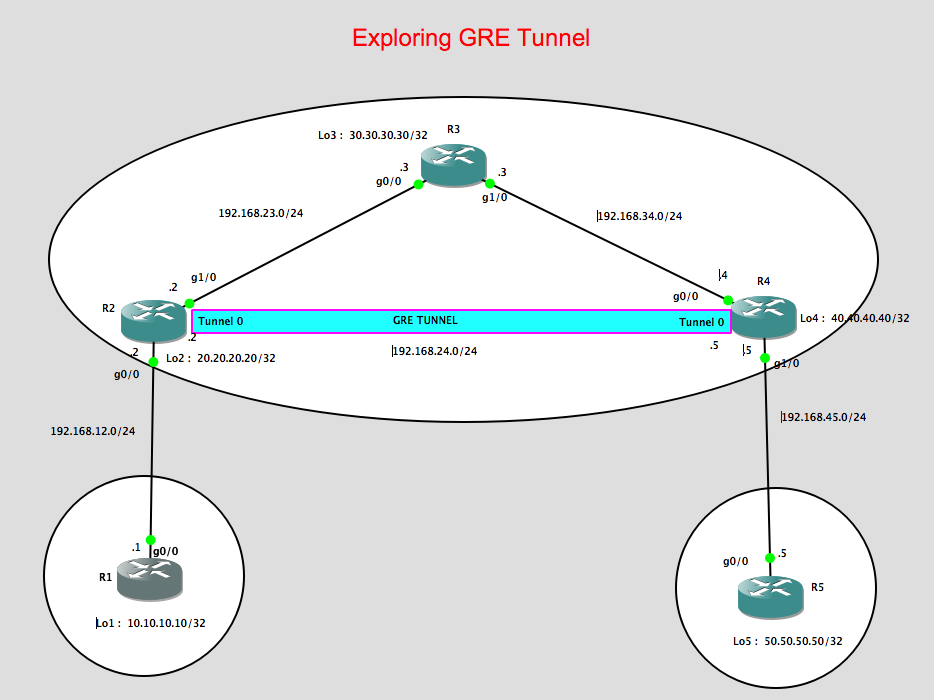
This post is all about GRE Tunneling and how it could be used to route traffic between two remote locations through a service provider network. On this networking lab, I’m gonna explore how GRE tunneling can be configured on a provider edge router, e.g. in my lab is showing as R2 towards another provider edge router R4 and route the customer traffic.
Lab topology:
Some considerations for this lab:
1. R2, R3, R4 will be running OSPF as the IGP to make the loopbacks of both both R2 and R4 reachable.
2. The loopbacks of R2 and R4 will be use as the Tunnel source / Tunnel destinations, respectively.
3. IBGP will be run between R2 and R4 using the tunnel ip address in order to learned the prefix advertise by R1 (Loopback 1 IP address of 10.10.10.10/32) known to R5. In the same manner, we want that R1 will learn about 50.50.50.50/32 via BGP.
4. Configure next-hop-self on both R2 and R4. Since by default BGP routers will not change the next-hop ip address it learned from its BGP neighbours, the next-hop-self is required for both R2 and R4 so that the prefix that they learned from R1 and R5, respectively, will be updated with the correct next-hop ip address.
5. Configure GRE Tunnel between R2 and R4
Let me show the configurations for each device:
R1 Configurations:
R1#show run | sec router
router bgp 1
no synchronization
bgp log-neighbor-changes
network 10.10.10.10 mask 255.255.255.255
neighbor 192.168.12.2 remote-as 234
no auto-summary
R1#
R2 Configurations:
R2#show run | sec router
router ospf 1
log-adjacency-changes
network 20.20.20.20 0.0.0.0 area 0
network 192.168.23.0 0.0.0.255 area 0
R2#show run | sec router
router bgp 234
no synchronization
bgp log-neighbor-changes
network 20.20.20.20 mask 255.255.255.255
neighbor 192.168.12.1 remote-as 1
no auto-summary
p.p1 {margin: 0.0px 0.0px 0.0px 0.0px; font: 11.0px Menlo; color: #000000; background-color: #ffffff} span.s1 {font-variant-ligatures: no-common-ligatures}
R2#
R3 Configurations:
p.p1 {margin: 0.0px 0.0px 0.0px 0.0px; font: 11.0px Menlo; color: #000000; background-color: #ffffff} span.s1 {font-variant-ligatures: no-common-ligatures}
R3#show run | sec router
router ospf 1
log-adjacency-changes
network 192.168.23.0 0.0.0.255 area 0
network 192.168.34.0 0.0.0.255 area 0
R3#
R4 Configurations:
p.p1 {margin: 0.0px 0.0px 0.0px 0.0px; font: 11.0px Menlo; color: #000000; background-color: #ffffff} span.s1 {font-variant-ligatures: no-common-ligatures}
R4#show run | sec router
router ospf 1
log-adjacency-changes
network 40.40.40.40 0.0.0.0 area 0
network 192.168.34.0 0.0.0.255 area 0
R4#show run | sec router
router bgp 234
no synchronization
bgp log-neighbor-changes
network 40.40.40.40 mask 255.255.255.255
neighbor 192.168.45.5 remote-as 5
no auto-summary
R4#
R5 Configurations:
R5#show run | sec router
router bgp 5
no synchronization
bgp log-neighbor-changes
network 50.50.50.50 mask 255.255.255.255
neighbor 192.168.45.4 remote-as 234
no auto-summary
p.p1 {margin: 0.0px 0.0px 0.0px 0.0px; font: 11.0px Menlo; color: #000000; background-color: #ffffff} span.s1 {font-variant-ligatures: no-common-ligatures}
R5#
eBGP is established between R1 and R2:
R1#show ip bgp summary
BGP router identifier 10.10.10.10, local AS number 1
BGP table version is 5, main routing table version 5
4 network entries using 480 bytes of memory
4 path entries using 208 bytes of memory
4/4 BGP path/bestpath attribute entries using 496 bytes of memory
2 BGP AS-PATH entries using 48 bytes of memory
0 BGP route-map cache entries using 0 bytes of memory
0 BGP filter-list cache entries using 0 bytes of memory
BGP using 1232 total bytes of memory
BGP activity 4/0 prefixes, 4/0 paths, scan interval 60 secs
Neighbor V AS MsgRcvd MsgSent TblVer InQ OutQ Up/Down State/PfxRcd
192.168.12.2 4 234 102 101 5 0 0 01:27:28 3
p.p1 {margin: 0.0px 0.0px 0.0px 0.0px; font: 11.0px Menlo; color: #000000; background-color: #ffffff} p.p2 {margin: 0.0px 0.0px 0.0px 0.0px; font: 11.0px Menlo; color: #000000; background-color: #ffffff; min-height: 13.0px} span.s1 {font-variant-ligatures: no-common-ligatures}
R1#
eBGP is established between R2 and R1 as shown below:
R2#show ip bgp summary
BGP router identifier 20.20.20.20, local AS number 234
BGP table version is 6, main routing table version 6
4 network entries using 480 bytes of memory
4 path entries using 208 bytes of memory
4/4 BGP path/bestpath attribute entries using 496 bytes of memory
2 BGP AS-PATH entries using 48 bytes of memory
0 BGP route-map cache entries using 0 bytes of memory
0 BGP filter-list cache entries using 0 bytes of memory
BGP using 1232 total bytes of memory
BGP activity 4/0 prefixes, 4/0 paths, scan interval 60 secs
Neighbor V AS MsgRcvd MsgSent TblVer InQ OutQ Up/Down State/PfxRcd
192.168.12.1 4 1 108 109 6 0 0 01:33:56 1
p.p1 {margin: 0.0px 0.0px 0.0px 0.0px; font: 11.0px Menlo; color: #000000; background-color: #ffffff} p.p2 {margin: 0.0px 0.0px 0.0px 0.0px; font: 11.0px Menlo; color: #000000; background-color: #ffffff; min-height: 13.0px} span.s1 {font-variant-ligatures: no-common-ligatures}
R2#
Also OSPF neighbour is formed between R2 and R3 through the loopback address.
R2#show ip ospf neighbor
Neighbor ID Pri State Dead Time Address Interface
30.30.30.30 1 FULL/BDR 00:00:37 192.168.23.3 GigabitEthernet1/0
p.p1 {margin: 0.0px 0.0px 0.0px 0.0px; font: 11.0px Menlo; color: #000000; background-color: #ffffff} p.p2 {margin: 0.0px 0.0px 0.0px 0.0px; font: 11.0px Menlo; color: #000000; background-color: #ffffff; min-height: 13.0px} span.s1 {font-variant-ligatures: no-common-ligatures}
R2#
Similarly R3 are forming the OSPF neighbours with R2 and R4:
R3#show ip ospf neighbor
Neighbor ID Pri State Dead Time Address Interface
40.40.40.40 1 FULL/DR 00:00:37 192.168.34.4 GigabitEthernet1/0
20.20.20.20 1 FULL/DR 00:00:37 192.168.23.2 GigabitEthernet0/0
p.p1 {margin: 0.0px 0.0px 0.0px 0.0px; font: 11.0px Menlo; color: #000000; background-color: #ffffff} p.p2 {margin: 0.0px 0.0px 0.0px 0.0px; font: 11.0px Menlo; color: #000000; background-color: #ffffff; min-height: 13.0px} span.s1 {font-variant-ligatures: no-common-ligatures}
R3#
For R4, we can see below that OSPF is formed towards R3 while eBGP is formed towards R5.
R4#show ip ospf neighbor
Neighbor ID Pri State Dead Time Address Interface
30.30.30.30 1 FULL/BDR 00:00:31 192.168.34.3 GigabitEthernet0/0
R4#
eBGP between R4 and R5:
R4#show ip bgp summary
BGP router identifier 40.40.40.40, local AS number 234
BGP table version is 6, main routing table version 6
4 network entries using 480 bytes of memory
4 path entries using 208 bytes of memory
4/4 BGP path/bestpath attribute entries using 496 bytes of memory
2 BGP AS-PATH entries using 48 bytes of memory
0 BGP route-map cache entries using 0 bytes of memory
0 BGP filter-list cache entries using 0 bytes of memory
BGP using 1232 total bytes of memory
BGP activity 4/0 prefixes, 4/0 paths, scan interval 60 secs
Neighbor V AS MsgRcvd MsgSent TblVer InQ OutQ Up/Down State/PfxRcd
192.168.45.5 4 5 99 100 6 0 0 01:26:15 1
p.p1 {margin: 0.0px 0.0px 0.0px 0.0px; font: 11.0px Menlo; color: #000000; background-color: #ffffff} p.p2 {margin: 0.0px 0.0px 0.0px 0.0px; font: 11.0px Menlo; color: #000000; background-color: #ffffff; min-height: 13.0px} span.s1 {font-variant-ligatures: no-common-ligatures}
R4#
Looking at R5, we can observed thart eBGP is also formed towards R4:
R5#show ip bgp summary
BGP router identifier 50.50.50.50, local AS number 5
BGP table version is 5, main routing table version 5
4 network entries using 480 bytes of memory
4 path entries using 208 bytes of memory
4/4 BGP path/bestpath attribute entries using 496 bytes of memory
2 BGP AS-PATH entries using 48 bytes of memory
0 BGP route-map cache entries using 0 bytes of memory
0 BGP filter-list cache entries using 0 bytes of memory
BGP using 1232 total bytes of memory
BGP activity 4/0 prefixes, 4/0 paths, scan interval 60 secs
Neighbor V AS MsgRcvd MsgSent TblVer InQ OutQ Up/Down State/PfxRcd
192.168.45.4 4 234 103 102 5 0 0 01:28:48 3
p.p1 {margin: 0.0px 0.0px 0.0px 0.0px; font: 11.0px Menlo; color: #000000; background-color: #ffffff} p.p2 {margin: 0.0px 0.0px 0.0px 0.0px; font: 11.0px Menlo; color: #000000; background-color: #ffffff; min-height: 13.0px} span.s1 {font-variant-ligatures: no-common-ligatures}
R5#
Now here’s the interesting part, we need to build the GRE tunnels between R2 and R4 but we need to ensure that loopback interface of both R2 and R4 is reachable.
I would expect that the loopback will be reachable via OSPF on both routers. Let’s check the below verifications:
R2#show ip route ospf
Codes: L – local, C – connected, S – static, R – RIP, M – mobile, B – BGP
D – EIGRP, EX – EIGRP external, O – OSPF, IA – OSPF inter area
N1 – OSPF NSSA external type 1, N2 – OSPF NSSA external type 2
E1 – OSPF external type 1, E2 – OSPF external type 2
i – IS-IS, su – IS-IS summary, L1 – IS-IS level-1, L2 – IS-IS level-2
ia – IS-IS inter area, * – candidate default, U – per-user static route
o – ODR, P – periodic downloaded static route, + – replicated route
Gateway of last resort is not set
40.0.0.0/32 is subnetted, 1 subnets
O 40.40.40.40 [110/3] via 192.168.23.3, 01:27:02, GigabitEthernet1/0
O 192.168.34.0/24 [110/2] via 192.168.23.3, 01:29:28, GigabitEthernet1/0
R2#
R2#ping 40.40.40.40 source 20.20.20.20
Type escape sequence to abort.
Sending 5, 100-byte ICMP Echos to 40.40.40.40, timeout is 2 seconds:
Packet sent with a source address of 20.20.20.20
!!!!!
Success rate is 100 percent (5/5), round-trip min/avg/max = 16/28/44 ms
p.p1 {margin: 0.0px 0.0px 0.0px 0.0px; font: 11.0px Menlo; color: #000000; background-color: #ffffff} p.p2 {margin: 0.0px 0.0px 0.0px 0.0px; font: 11.0px Menlo; color: #000000; background-color: #ffffff; min-height: 13.0px} span.s1 {font-variant-ligatures: no-common-ligatures}
R2#
So as observed the loopback of R4 is reachable from R2.
Now Let’s configure the GRE Tunnels between R2 and R4:
R2#show run int tunnel 0
Building configuration…
Current configuration : 126 bytes
!
interface Tunnel0
ip address 192.168.24.2 255.255.255.0
tunnel source 20.20.20.20
tunnel destination 40.40.40.40
p.p1 {margin: 0.0px 0.0px 0.0px 0.0px; font: 11.0px Menlo; color: #000000; background-color: #ffffff} p.p2 {margin: 0.0px 0.0px 0.0px 0.0px; font: 11.0px Menlo; color: #000000; background-color: #ffffff; min-height: 13.0px} span.s1 {font-variant-ligatures: no-common-ligatures}
!
R4#show run int tunnel 0
Building configuration…
Current configuration : 126 bytes
!
interface Tunnel0
ip address 192.168.24.4 255.255.255.0
tunnel source 40.40.40.40
tunnel destination 20.20.20.20
!
p.p1 {margin: 0.0px 0.0px 0.0px 0.0px; font: 11.0px Menlo; color: #000000; background-color: #ffffff} p.p2 {margin: 0.0px 0.0px 0.0px 0.0px; font: 11.0px Menlo; color: #000000; background-color: #ffffff; min-height: 13.0px} span.s1 {font-variant-ligatures: no-common-ligatures}
end
So as observed above, the tunnel source for R2 is its own loopback address and the destination is the loopback of R4. I have assigned the ip address on each tunnel as per the IP addressing design
which is 192.168.24.2/24 for R2 and 192.168.24.4/24 for R4.
Let’s verify the Tunnel interface status,
R2#show ip int brief
Interface IP-Address OK? Method Status Protocol
Ethernet0/0 unassigned YES unset administratively down down
GigabitEthernet0/0 192.168.12.2 YES manual up up
GigabitEthernet1/0 192.168.23.2 YES manual up up
Loopback2 20.20.20.20 YES manual up up
Tunnel0 192.168.24.2 YES manual up up
p.p1 {margin: 0.0px 0.0px 0.0px 0.0px; font: 11.0px Menlo; color: #000000; background-color: #ffffff} span.s1 {font-variant-ligatures: no-common-ligatures}
R2#
R4#show ip int brief
Interface IP-Address OK? Method Status Protocol
Ethernet0/0 unassigned YES unset administratively down down
GigabitEthernet0/0 192.168.34.4 YES manual up up
GigabitEthernet1/0 192.168.45.4 YES manual up up
Loopback4 40.40.40.40 YES manual up up
Tunnel0 192.168.24.4 YES manual up up
p.p1 {margin: 0.0px 0.0px 0.0px 0.0px; font: 11.0px Menlo; color: #000000; background-color: #ffffff} span.s1 {font-variant-ligatures: no-common-ligatures}
R4#
As a test, i can ping the tunnel address of R4 from R2 as shown below,
R2#ping 192.168.24.4 source 192.168.24.2
Type escape sequence to abort.
Sending 5, 100-byte ICMP Echos to 192.168.24.4, timeout is 2 seconds:
Packet sent with a source address of 192.168.24.2
!!!!!
Success rate is 100 percent (5/5), round-trip min/avg/max = 16/27/32 ms
p.p1 {margin: 0.0px 0.0px 0.0px 0.0px; font: 11.0px Menlo; color: #000000; background-color: #ffffff} p.p2 {margin: 0.0px 0.0px 0.0px 0.0px; font: 11.0px Menlo; color: #000000; background-color: #ffffff; min-height: 13.0px} span.s1 {font-variant-ligatures: no-common-ligatures}
R2#
Now its time to configured iBGP between R2 and R4 so that the prefix advertise by R1 and R5 will be reachable.
p.p1 {margin: 0.0px 0.0px 0.0px 0.0px; font: 11.0px Menlo; color: #000000; background-color: #ffffff} span.s1 {font-variant-ligatures: no-common-ligatures}
R2#show run | sec router
router bgp 234
no synchronization
bgp log-neighbor-changes
network 20.20.20.20 mask 255.255.255.255
neighbor 192.168.12.1 remote-as 1
neighbor 192.168.24.4 remote-as 234
neighbor 192.168.24.4 next-hop-self
p.p1 {margin: 0.0px 0.0px 0.0px 0.0px; font: 11.0px Menlo; color: #000000; background-color: #ffffff} span.s1 {font-variant-ligatures: no-common-ligatures}
no auto-summary
R4#show run | sec router
router bgp 234
no synchronization
bgp log-neighbor-changes
network 40.40.40.40 mask 255.255.255.255
neighbor 192.168.24.2 remote-as 234
neighbor 192.168.24.2 next-hop-self
neighbor 192.168.45.5 remote-as 5
p.p1 {margin: 0.0px 0.0px 0.0px 0.0px; font: 11.0px Menlo; color: #000000; background-color: #ffffff} span.s1 {font-variant-ligatures: no-common-ligatures}
no auto-summary
As seen above, I have configured iBGP between R2 and R4. Let’s try to check the BGP status and the advertised/received routes:
R2#show ip bgp summary
BGP router identifier 20.20.20.20, local AS number 234
BGP table version is 6, main routing table version 6
4 network entries using 480 bytes of memory
4 path entries using 208 bytes of memory
4/4 BGP path/bestpath attribute entries using 496 bytes of memory
2 BGP AS-PATH entries using 48 bytes of memory
0 BGP route-map cache entries using 0 bytes of memory
0 BGP filter-list cache entries using 0 bytes of memory
BGP using 1232 total bytes of memory
BGP activity 4/0 prefixes, 4/0 paths, scan interval 60 secs
Neighbor V AS MsgRcvd MsgSent TblVer InQ OutQ Up/Down State/PfxRcd
192.168.12.1 4 1 124 125 6 0 0 01:48:49 1
192.168.24.4 4 234 108 106 6 0 0 01:28:55 2
p.p1 {margin: 0.0px 0.0px 0.0px 0.0px; font: 11.0px Menlo; color: #000000; background-color: #ffffff} p.p2 {margin: 0.0px 0.0px 0.0px 0.0px; font: 11.0px Menlo; color: #000000; background-color: #ffffff; min-height: 13.0px} span.s1 {font-variant-ligatures: no-common-ligatures}
R2#
R4#show ip bgp summary
BGP router identifier 40.40.40.40, local AS number 234
BGP table version is 6, main routing table version 6
4 network entries using 480 bytes of memory
4 path entries using 208 bytes of memory
4/4 BGP path/bestpath attribute entries using 496 bytes of memory
2 BGP AS-PATH entries using 48 bytes of memory
0 BGP route-map cache entries using 0 bytes of memory
0 BGP filter-list cache entries using 0 bytes of memory
BGP using 1232 total bytes of memory
BGP activity 4/0 prefixes, 4/0 paths, scan interval 60 secs
Neighbor V AS MsgRcvd MsgSent TblVer InQ OutQ Up/Down State/PfxRcd
192.168.24.2 4 234 106 109 6 0 0 01:29:26 2
192.168.45.5 4 5 117 118 6 0 0 01:43:00 1
p.p1 {margin: 0.0px 0.0px 0.0px 0.0px; font: 11.0px Menlo; color: #000000; background-color: #ffffff} p.p2 {margin: 0.0px 0.0px 0.0px 0.0px; font: 11.0px Menlo; color: #000000; background-color: #ffffff; min-height: 13.0px} span.s1 {font-variant-ligatures: no-common-ligatures}
R4#
Let’s check the prefix advertise by R2 and R4 by this time:
R2#show ip route bgp
Codes: L – local, C – connected, S – static, R – RIP, M – mobile, B – BGP
D – EIGRP, EX – EIGRP external, O – OSPF, IA – OSPF inter area
N1 – OSPF NSSA external type 1, N2 – OSPF NSSA external type 2
E1 – OSPF external type 1, E2 – OSPF external type 2
i – IS-IS, su – IS-IS summary, L1 – IS-IS level-1, L2 – IS-IS level-2
ia – IS-IS inter area, * – candidate default, U – per-user static route
o – ODR, P – periodic downloaded static route, + – replicated route
Gateway of last resort is not set
10.0.0.0/32 is subnetted, 1 subnets
B 10.10.10.10 [20/0] via 192.168.12.1, 01:50:51
50.0.0.0/32 is subnetted, 1 subnets
B 50.50.50.50 [200/0] via 192.168.24.4, 01:28:45
p.p1 {margin: 0.0px 0.0px 0.0px 0.0px; font: 11.0px Menlo; color: #000000; background-color: #ffffff} p.p2 {margin: 0.0px 0.0px 0.0px 0.0px; font: 11.0px Menlo; color: #000000; background-color: #ffffff; min-height: 13.0px} span.s1 {font-variant-ligatures: no-common-ligatures}
R2#
With the ” next-hop-self “ configured on R2, we can see that the next hop address to reach 50.50.50.50/32 is via the tunnel ip address of R4. R4 have changed this next-hop ip address when it advertise the prefix to R2.
As we can see below the next hop IP address learned by R4 with the prefix 50.50.50.50/32 is 192.168.45.5 which is R5.
R4#show ip route bgp
Codes: L – local, C – connected, S – static, R – RIP, M – mobile, B – BGP
D – EIGRP, EX – EIGRP external, O – OSPF, IA – OSPF inter area
N1 – OSPF NSSA external type 1, N2 – OSPF NSSA external type 2
E1 – OSPF external type 1, E2 – OSPF external type 2
i – IS-IS, su – IS-IS summary, L1 – IS-IS level-1, L2 – IS-IS level-2
ia – IS-IS inter area, * – candidate default, U – per-user static route
o – ODR, P – periodic downloaded static route, + – replicated route
Gateway of last resort is not set
10.0.0.0/32 is subnetted, 1 subnets
B 10.10.10.10 [200/0] via 192.168.24.2, 01:29:51
50.0.0.0/32 is subnetted, 1 subnets
B 50.50.50.50 [20/0] via 192.168.45.5, 01:45:08
p.p1 {margin: 0.0px 0.0px 0.0px 0.0px; font: 11.0px Menlo; color: #000000; background-color: #ffffff} p.p2 {margin: 0.0px 0.0px 0.0px 0.0px; font: 11.0px Menlo; color: #000000; background-color: #ffffff; min-height: 13.0px} span.s1 {font-variant-ligatures: no-common-ligatures}
R4#
So both routers are receiving the prefixes advertised by R1 and R5 and next hop change accordingly.
Thus we would expect that with the eBGP session established between R1 & R2 and R4 & R5, we could see on the BGP routing table the loopbacks for both R1 and R5.
R1#show ip route bgp
Codes: L – local, C – connected, S – static, R – RIP, M – mobile, B – BGP
D – EIGRP, EX – EIGRP external, O – OSPF, IA – OSPF inter area
N1 – OSPF NSSA external type 1, N2 – OSPF NSSA external type 2
E1 – OSPF external type 1, E2 – OSPF external type 2
i – IS-IS, su – IS-IS summary, L1 – IS-IS level-1, L2 – IS-IS level-2
ia – IS-IS inter area, * – candidate default, U – per-user static route
o – ODR, P – periodic downloaded static route, + – replicated route
Gateway of last resort is not set
20.0.0.0/32 is subnetted, 1 subnets
B 20.20.20.20 [20/0] via 192.168.12.2, 07:07:11
40.0.0.0/32 is subnetted, 1 subnets
B 40.40.40.40 [20/0] via 192.168.12.2, 06:47:34
50.0.0.0/32 is subnetted, 1 subnets
B 50.50.50.50 [20/0] via 192.168.12.2, 06:45:22
p.p1 {margin: 0.0px 0.0px 0.0px 0.0px; font: 11.0px Menlo; color: #000000; background-color: #ffffff} p.p2 {margin: 0.0px 0.0px 0.0px 0.0px; font: 11.0px Menlo; color: #000000; background-color: #ffffff; min-height: 13.0px} span.s1 {font-variant-ligatures: no-common-ligatures}
R1#
As we see below, we can reach the loopback of R2 from R5 so this means we have established a working GRE Tunnels.
R5#ping 10.10.10.10 source 50.50.50.50
Type escape sequence to abort.
Sending 5, 100-byte ICMP Echos to 10.10.10.10, timeout is 2 seconds:
Packet sent with a source address of 50.50.50.50
!!!!!
Success rate is 100 percent (5/5), round-trip min/avg/max = 48/56/68 ms
R5#traceroute 10.10.10.10 source 50.50.50.50
Type escape sequence to abort.
Tracing the route to 10.10.10.10
1 192.168.45.4 12 msec 28 msec 24 msec
2 192.168.24.2 44 msec 12 msec 72 msec
3 192.168.12.1 48 msec 44 msec 56 msec
p.p1 {margin: 0.0px 0.0px 0.0px 0.0px; font: 11.0px Menlo; color: #000000; background-color: #ffffff} p.p2 {margin: 0.0px 0.0px 0.0px 0.0px; font: 11.0px Menlo; color: #000000; background-color: #ffffff; min-height: 13.0px} span.s1 {font-variant-ligatures: no-common-ligatures}
R5#
Take away for this lab:
1. IGP was used as the routing protocol to advertise the loopbacks in this case, OSPF is used.
2. We have decided to used BGP to advertise the prefix on R1 & R5 through the GRE tunnel devices ( R2 & R4).
3. Next-Hop-Self is necessary to advertised the prefix to the other side of the network otherwise reachability will not be established.
p.p1 {margin: 0.0px 0.0px 0.0px 0.0px; font: 11.0px Menlo; color: #000000; background-color: #ffffff} span.s1 {font-variant-ligatures: no-common-ligatures} p.p1 {margin: 0.0px 0.0px 0.0px 0.0px; font: 11.0px Menlo; color: #000000; background-color: #ffffff} span.s1 {font-variant-ligatures: no-common-ligatures} p.p1 {margin: 0.0px 0.0px 0.0px 0.0px; font: 11.0px Menlo; color: #000000; background-color: #ffffff} p.p2 {margin: 0.0px 0.0px 0.0px 0.0px; font: 11.0px Menlo; color: #000000; background-color: #ffffff; min-height: 13.0px} span.s1 {font-variant-ligatures: no-common-ligatures}

Leave a comment